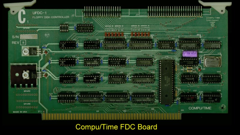
The UFDC-1 interfaced to the IEEE/696 S-100 bus and provided for connecting
up to four floppy disk drives. The drives could be any combination of 5" and
8" drives with ANSI standard interfaces. Single or double density and single
or double sided drives were supportedl. The UFDC-I utilizes the
Western Digital 1795 Floppy Disk Cont roller chip.
The UFDC-I synchronizes the processor to disk data transfers by means of
wait states. When the data register of the 1795 was addressed by the CPU
(detected by I/O port decode) the CPU was put into a wait state until the
UFDC- I signals that it is ready for a data transfer. The 1795 contained a
control/status register, a track register, and a sector register in addition
to the read/write data register. It performed the functions associated with
reading and writing bit serial data to the floppy disk drives. The 1795 also
performed functions associated with positioning the disk heads and locating
data sectors on the disk and also provided for formatting blank disks.
The UFDC-1 contained an external control port and a status port. The control
port was used to activate the drive select logic, to select a drive for
access by the 1795. The density and disk side were also selected by the
control port. The control port could enable or disable the wait state
circuitry. The status port provided information about the disk drives to the
system. Option jumpers were included to describe the physical
characteristics of each selected disk drive. The option jumpers for the
drive selected by the control port were visible at the status port. The
jumpers indicated if the drive was a 5" or 8", and indicated the step rate
value for head movement on that drive. Additional signals were provided to
indicate drive and 1795 interface status.
The UFDC-I used all digital data circuitry for write pre-compensation and
read data separation. A synchronous clock distribution scheme was used so
that the 1795 and all data circuitry clocks were derived from the same
source. The clock used by the 1795 and the data separator were determined by
the 5/8 option jumper for the selected drive, and by the sing1e/doub1e
density signal from the control port.
The bard was very similar in concept and design to the
Versafloppy II FDC.